
Creating a pattern definition
On each lace ground page, below the pair and thread diagrams, you will find an area labelled Edit pattern. You can use the controls in this area to modify an existing pattern (add a headside or a footside, for example) or to create a new pattern.
New Pattern Tutorial
We will use Rose ground as an example and define a pattern for it from scratch. There are many ways to draw the pair diagram for Rose ground. One way to think of it is as a checkerboard with a diamond inside each of the black squares.
Define the base pattern
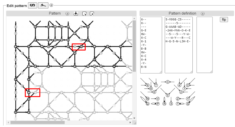
A lace ground consists of a small pattern that is repeated, like a wallpaper or printed fabric pattern, to cover the area you need to fill. This small pattern is called a base tile. The area labelled Pattern definition contains three text boxes. The left and right boxes define the headside and footside. We will discuss them later. The middle box defines the base tile.
The first step is to look at a ground and identify the base tile. There are many ways to do this and over the course of this tutorial, we will show a few of them.
Simple arrangement
The easiest approach is to start with a printed copy of the pattern. Pick a spot on the pattern and look in the horizontal direction until you find an exact copy of this spot. Draw a line. Now return to the original spot and look straight down until you find another exact copy of this spot. Draw a line and complete the rectangle created by these two lines.
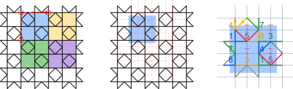
Each rectangle highlights one repeat of the Rose pattern. For convenience, on the right of the image above we have moved the rectangles slightly so that it is easy to see all the intersections of pairs within a rectangle (no intersection lies on the edge of a rectangle).
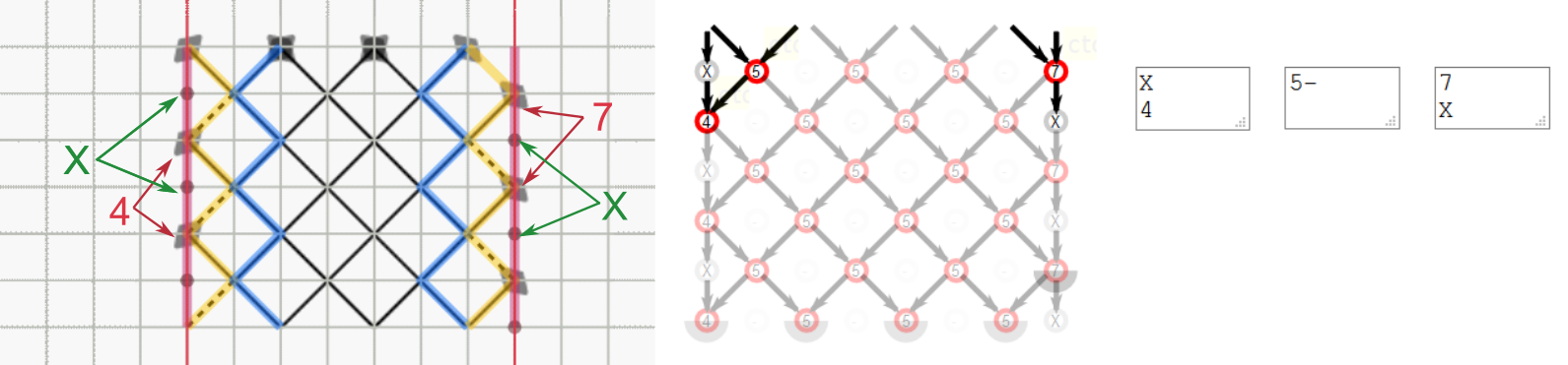
Next we will map the pairs in the lace ground to a grid. Draw a grid on top of the base tile on your paper copy as shown by the red dashed lines in the middle image above. Within one repeat rectangle, the intersections lie on four columns and four rows.
For each position in the grid, we assign a symbol. The symbol specifies the angle and direction of the two pairs that are coming in to meet at that row/column position. The meaning of each symbol is shown in the Cheat sheet just below the Pattern definition area. For example, in row 1/column 1 the yellow arrows correspond to the symbol 4 which is a pair coming straight down and a pair coming diagonally down pointing south-west. Similarly, in row 3/column 2, there is no intersection of pairs which we represent by the symbol -.
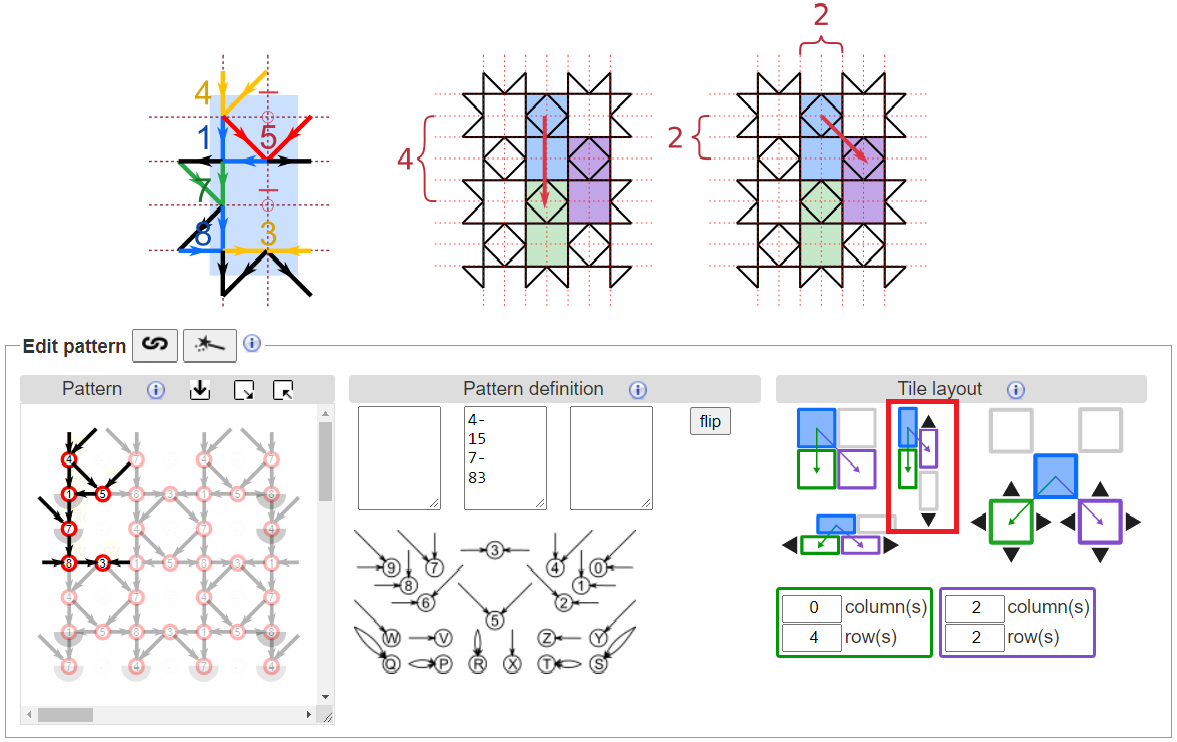
We can now fill in the middle section of the Pattern definition area. Notice that the pattern diagram updates to match the symbols as soon as you click outside of the text box.

Glue copies together
Now we need to specify how to connect the many copies of this pattern together. This is done in the area labelled Tile layout. For a simple arrangement, just click on the solid blue square in the drawing of a simple tiling as shown in the figure below.
Notice that this changes the numbers in the green and purple boxes at the bottom of the Tile layout area. Let’s discuss what these numbers mean. Consider several meters of a lace edging. The pattern for the edging is not several meters long. It is a smaller pattern that you repeat over and over again by sliding the pattern along in one direction. This gives a long strip. To make a larger rectangular sample from a small pattern, we need to slide the pattern in two directions.
Consider the image below. Red dashed lines show the grid overlaid on the pattern.
![]()
To position the blue rectangle on top of the green rectangle, we must slide the blue rectangle down 4 rows. To position the blue rectangle on top of the purple rectangle, we must slide it right 4 columns and down 4 rows. These translation distances are the numbers that appear in the green and purple boxes. You can also edit these slide moves directly in the number fields.
Creating a smaller base tile
You might have noticed that in the simple tile arrangement, we actually have two “roses” in the base tile. We will now look at two ways to reduce the number of intersections in the base tile.
Brick arrangement
For some patterns, as shown for rose ground in the image below, the repeating rectangles can be arranged like vertical bricks. Notice that each brick contains only one “rose”.
For a vertical brick pattern first identify one brick and label each intersection with a symbol from the cheat sheet as we did for the simple tile. To glue the copies together to make a larger pattern, first click on the filled blue brick in the picture of vertical bricks.
If the pattern does not immediately align correctly, click on the black arrows above and below the second column of bricks to adjust how the two columns of bricks align. Each click will move the second column up or down by one row relative to the first column. Look at the pattern diagram to see how the copies move around.
Overlap arrangement
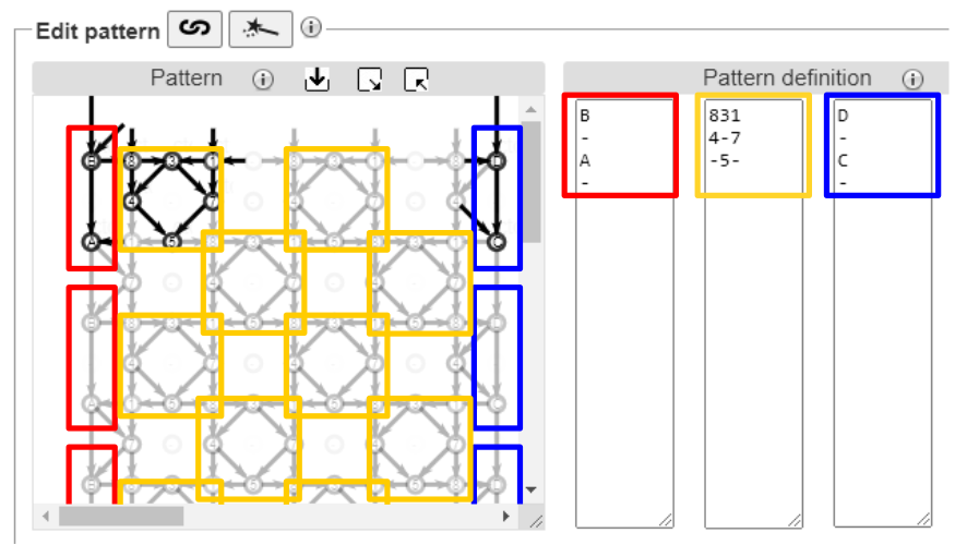
When a large part of the pattern is a hole, we can further decrease the size of the base tile using overlap. In this case, the base tile does not include the hole. In the figure below, the coloured squares each contain one copy of the pattern.
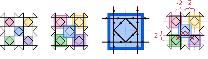
For the overlap layout, make the base pattern a little bit larger, as shown in the second drawing from the left, to encompass any intersections along its border. Notice that the squares overlap at the corners.
Apply a grid to the base pattern and assign symbols to each line intersection. This time we have three rows and three columns in the base pattern.
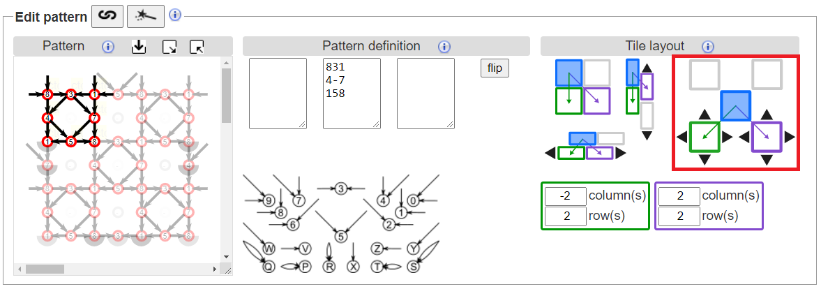
Finally, we arrange the copies. Click on the filled blue block in the image of a checkerboard. Initially, the copies will be placed corner to corner. Click on the black arrows around the green and purple blocks to nudge the copies so that they overlap as desired.
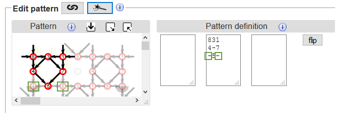
It is important to have only one copy of each stitch in the pattern, otherwise unexpected things can happen. Therefore, an important last step is to remove the duplicate stitches that appear in the overlapping corners. Replace the overlapped stitches in the bottom corners with as many -’s as required, as shown below in the green boxes.
Footside Tutorial
In the Edit pattern section, the central panel defines the ground, and the left and right side panels define the left and right footsides.
The leftmost edge of the central patch is determined by the leftmost column in the ground definition. If you want to change where the patch starts on the left, you must choose a different starting point for the base pattern and modify the ground definition accordingly.
The rightmost edge of the patch depends on the number of columns specified in the Swatch size. If you change the number of columns in the patch size, the right footside may no longer match correctly. Note that the number of columns required for the footsides are not included in the Swatch size. They are added on top of the width that you specify.
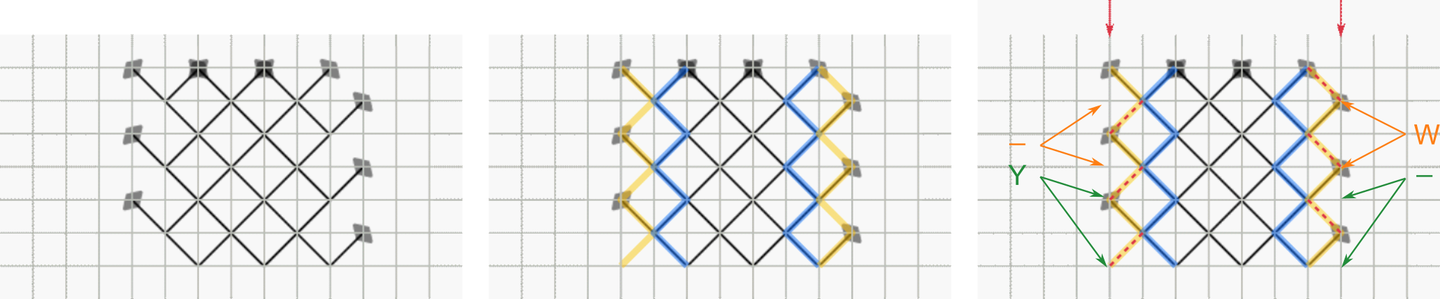
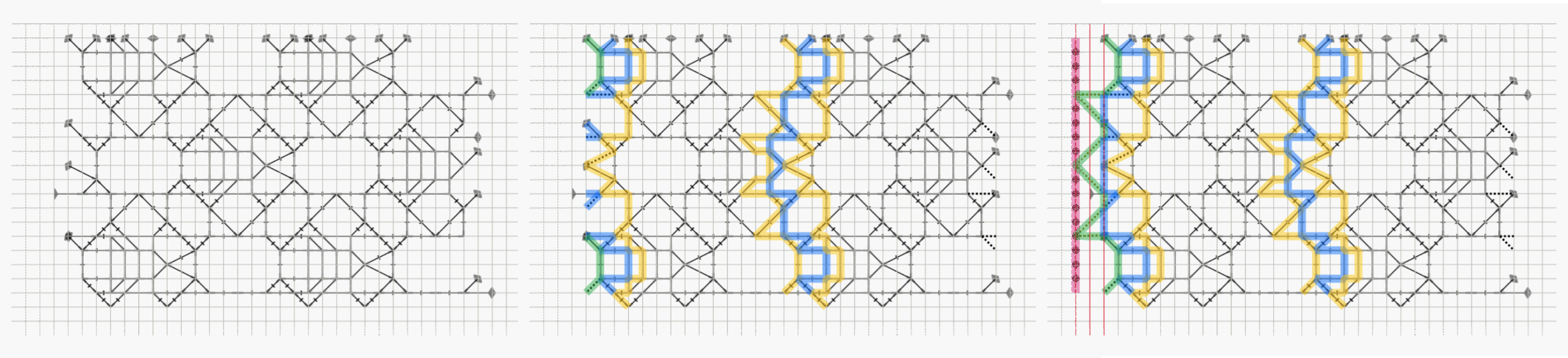
First, we will consider the simple example of Torchon Ground. Lay a square grid over the pair diagram. We must identify the loose ends of pairs along the edge and match them up where possible. To do this, we can use a “kissing path”. A kissing path follows one set of pairs through the pair diagram. When two pairs intersect, the kissing path does not cross over to the other side, it just touches the other pair (“kisses”) and continues. You can think of it as the path that a pair of threads follows if a turning stitch (cttct) is used at each intersection. The yellow and blue thick lines in the figure below highlight the kissing paths for the pairs at the edge of the pair diagram. Note that several incoming edges are missing on the yellow kissing path (dashed red lines). We can add them by labelling the incoming pair intersections using the symbols W, Y and - in the Cheat Sheet:
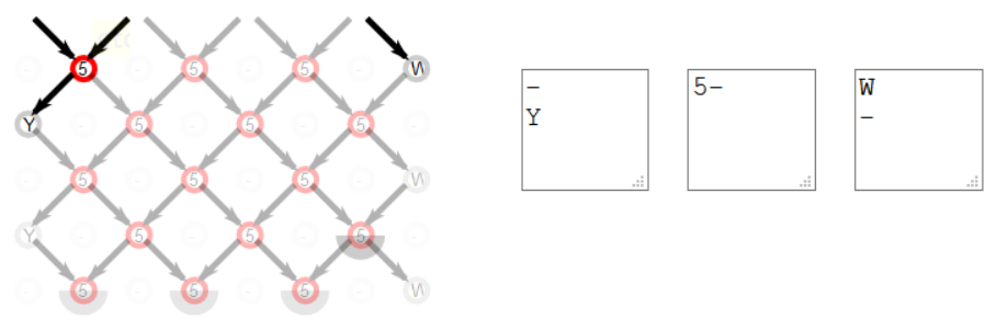
Below is the completed footside definition. Footside definitions are repeated in one direction, like a frieze pattern. In this example, the definition for the left footside of the Torchon ground is “-,Y” so the left footside will be “-,Y,-,Y,-,Y,…” for as many rows as are in the patch. Note that in this example, the footside definition has two rows while the ground definition only has one row. The ground and footside definitions may not always have the same number of rows.
Alternatively, we can make the edge straight by adding another pair of threads, shown in red below.
Now consider the more complicated example of G-4 in the Whiting sampler. We follow the same steps: lay a grid over the pair diagram and trace out the kissing paths on the left edge of the pattern. Note that this time the blue and green kissing paths are not complete; large sections are missing. We need to add intersections to complete the blue and green kissing paths. We can also add another kissing path, shown in red, to make a clean straight edge. In total, this footside requires three columns.
Below is G-4 with left footside. Notice the red box around “V,6” in the ground area of the pattern diagram. In the original definition, this was “-,L” which draws a long horizontal edge. The long horizontal edge sticks out on the left side of the patch. We can get a better looking footside by shortening this edge. In order to get a short edge on the left side of the patch, we changed the ground definition to use two short horizontal edges in a row (“V,6”) instead of one long edge (“-,L”). The symbols “V,6” and “-,L” give the same result in the thread diagram. On the footside, we can cut the ground pattern off at “6” which gives a nicer looking result (see red box around “C,6”, the “C” intersection is part of the footside. The “6” intersection is part of the ground). As an exercise, create the right footside.
You can also create a traditional footside that has several passives.
Thread diagram as pair diagram
In a typical pair diagram, two pairs intersect at each crossing and then continue. In a thread diagram, two threads meet at each crossing and then continue. So why not take a thread diagram and use it as a pair diagram? Using this technique, you can quickly create a new, usually more complex, pattern.
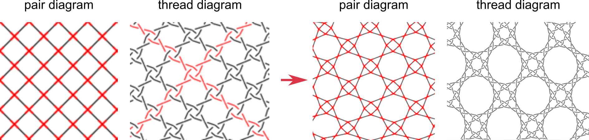
See the Droste effect tutorial for more information.